ViDRILO: The Visual and Depth Robot Indoor Localization with Objects information dataset
Documentation
How to cite ViDRILO
J. Martinez-Gomez, M. Cazorla, I. Garcia-Varea and V. Morell.- “ViDRILO: The Visual and Depth Robot Indoor Localization with Objects information dataset”. International Journal of Robotics Research. DOI: 10.1177/0278364915596058 2015
ViDRILO ToolBox
The ViDRILO dataset is released in conjunction with a MATLAB toolbox for its complete use. This toolbox includes a configuration file with all the information included in the dataset: paths and names of the RGB-D images, annotations for the room category of the scenes, and the presence/absence of the list of 15 objects. The toolbox also includes visualization features, statistics generation, and the capability of training a complete semantic localization system (using a combination of training sequence, classification model and image descriptors) and evaluate it against any dataset sequence. For a complete description of this toolbox, see the guide of use or visit the tools page.
Technical details
The ViDRILO dataset consists of five different sequences of RGB-D images acquired during a span of 12 months. These sequences differ in the path followed by the robot and the building where the acquisition was carried out. All the images were acquired using a Powerbot robot with an onboard kinect device. The overall characteristics for each one of the five sequences of the dataset are shown in the following Table.
| Sequence | #Frames | Building | Floors | Dark Rooms | Time Span |
| 1 | 2389 | A | 1st,2nd | 0/18 | 0 months |
| 2 | 4579 | A | 1st,2nd | 0/18 | 0 months |
| 3 | 2248 | A | 2nd | 4/13 | 3 months |
| 4 | 4826 | A | 1st,2nd | 6/18 | 6 months |
| 5 | 8412 | B | 1st,2nd | 0/20 | 12 months |
Groundtruth data
Each frame in the dataset consists of a visual image and a point cloud file representing the same scene. Both are labeled with the semantic category of the room where they were acquired, as well as the presence/absence for a list of 15 predefined objects appearing in the environments. Ten different room categories were considered and the following codes were used: CR (Corridor), HA (Hall), PO (Professor Office), SO (Student Office), TR (Technical Room), TO (Toilet), SE (Secretary Office), VC (Video Conference Room), WH (Warehouse), EA (Elevator Area). These categories are very common in most educational indoor buildings.
Fifteen different objects were considered, whose presence or lack is also annotated for each image in the dataset. These objects were selected because they all are typical objects easily found at any indoor environment, specially in an educational building. Moreover, their occurrence or not in an image can provide useful cues to detect the semantic category of the corresponding room. For instance, we would say we are placed in a toilet (without previous knowledge) if we already are aware of that the scene contains a hand-drier and/or a sink, and not a computer (for example).
See Rooms and Objects sections to see examples of these elements.
Acquisition Procedure
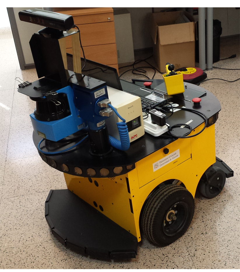
The whole dataset was acquired using a Powerbot robot with a Kinect device installed on top of it at a total height of 90 cm. (see Fig. 1). The robot was manually driven using a joystick, and a laptop connected to the Kinect camera was used to process and save the data.
The robot was continuously moving, following the path described below for each sequence, at an approximate mean linear velocity of 0.3 m/s. RGB-D images were acquired, processed and saved using the OpenNI tools and the Point Cloud Library (PCL). The acquisition process provided color images a with resolution of 640x480 pixels and point clouds with 307200 3D colored points. The point cloud was stored using the Point Cloud Data (PCD) format of the PCL library in binary format (PCD_V7).
Once each frame sequence was generated, it was entirely checked to avoid synchronization errors between visual and depth images, or missing data, rejecting bad data (color images without depth data and vice versa). All frames were manually labeled with the corresponding room category and the presence or absence of the list of 15 predefined objects.
Here we provide more details about the path followed by the robot during the acquisitions. Sequence 1 and 4 were generated following the path shown in Fig.2. The robot started capturing at position 1 (second floor), and went towards position 2 (the Elevator Area). With the elevator, it went down to position 3 (1st floor) and then to position 4 (end of the sequence). The complete path has a length of 352 meters. In these both sequences all robot turns were done clockwise. The sequence of obtained room categories was: PO, CR, SO, CR, PO, CR, SC, CR, TO, CR, HA, CR, TR, CR, EA, HA, CR, VC, CR, and WH.
Sequence 2 was acquired following the same but inverse path of sequence 1 (that is, starting at point 4 and finishing at point 1), and doing countclockwise turns, containing a total of 4578 frames. Regarding the path length, and the capturing time, they were very similar to the ones obtained for sequence 1. The list of room categories is correspondingly the opposite as the above mentioned for sequences 1 and 4. Sequence 3 was acquired following the same path as sequence 2, but only in the 2nd floor, starting at point 2 and finishing at point 1, containing a total of 2247 frames and also using counterclockwise turns. The path followed for sequence 3 has a length of 215 meters.
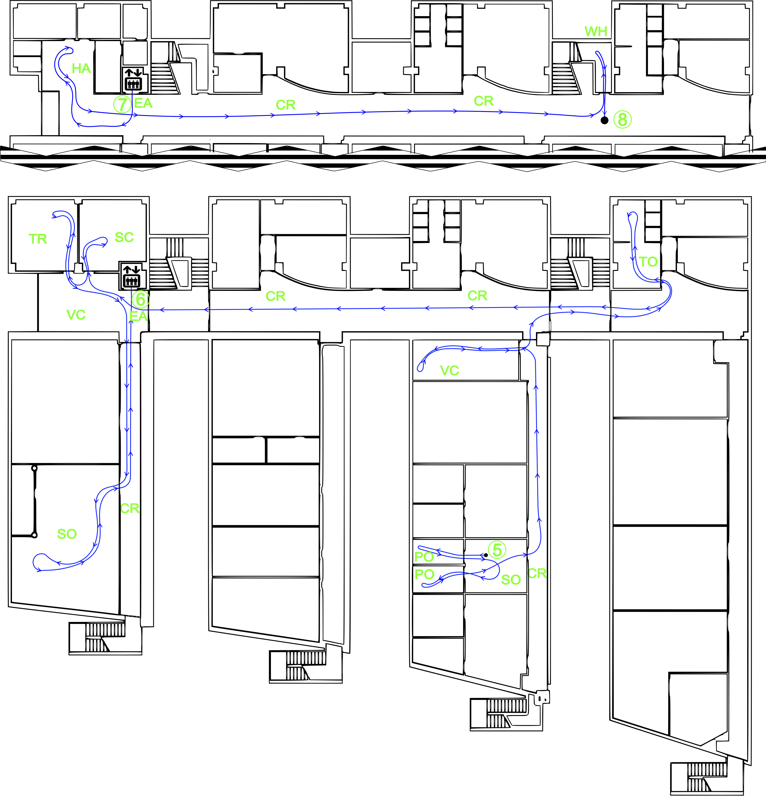
Finally, sequence 5 was generated in building B (Fig.3). The robot started at position 5 (2nd floor), and followed the path shown up to position 6, where with the elevator went down to position 7 (first floor), and then continued to position 8 (end of sequence). The robot travelled a path of about 320 meters with 8412 acquired frames. The order of room categories visited in this sequence was: PO, SO, PO, SO, CR, VC, CR, TO, CR, VC, SC, VC, TR, VC, CR, SO, CR, EA, HA, CR, WH.
Building A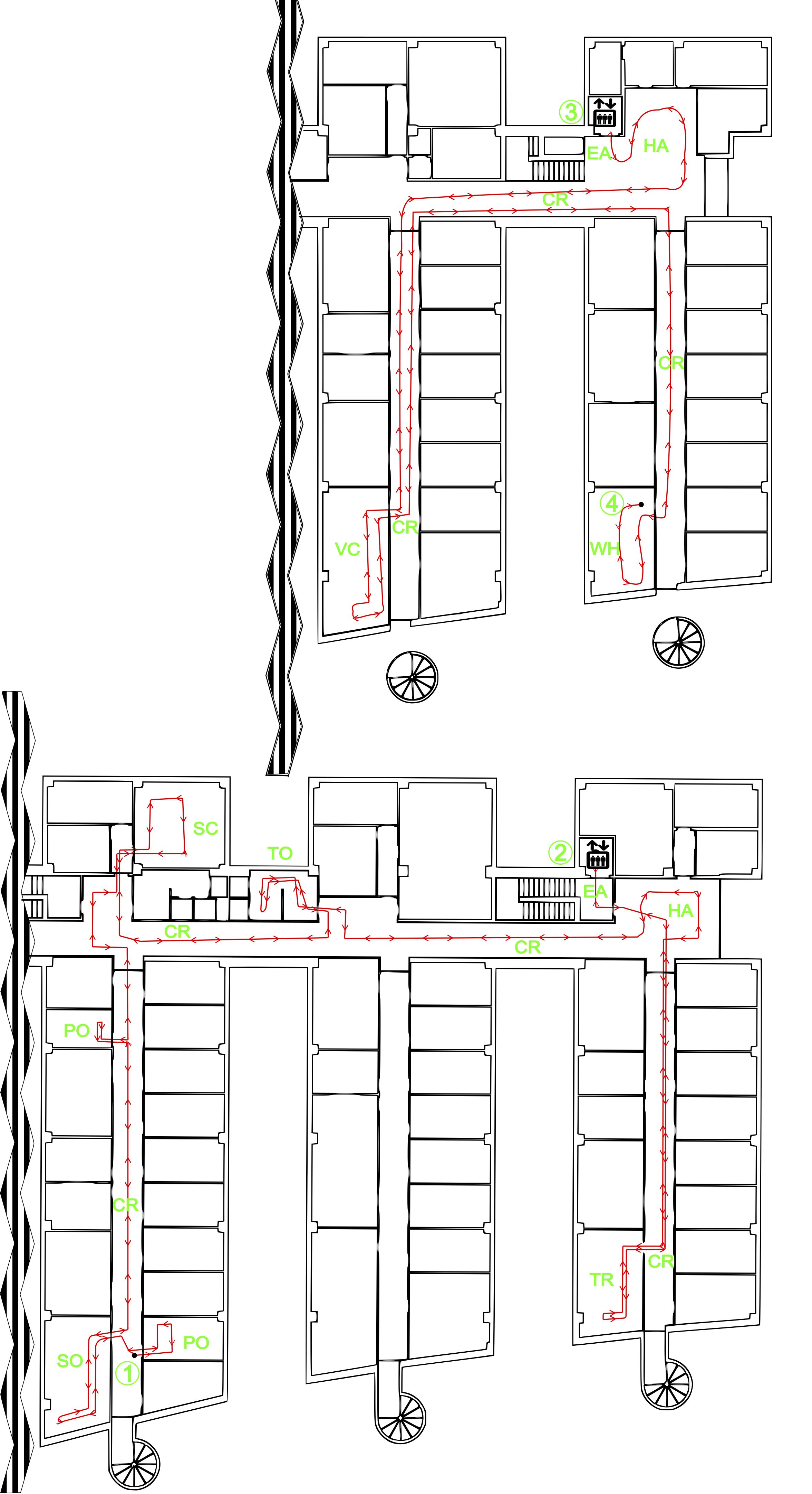
BuildingB